
Precision Machining CNC
Precision Machining CNC — DFM-first work from Dongguan, ±0.003 mm, CMM-verified. Tolerances: ±0.003 mm milling, ±0.002 mm turning — ISO 9001 / IATF 16949 verified.
Precision machining CNC is tolerance and DFM working together. This page covers how tolerances interact with DFM, ISO 2768, and the common DFM mistakes.
What is precision machining CNC?
Precision machining CNC is CNC machining applied to precision work — tolerances and DFM decided together, because every tight callout has a process cost. ISO 2768 classes set the defaults where a drawing is silent; explicit callouts set the rest.
Four choices drive cost silently: blanket tight tolerances (every dimension held to a premium band), thin walls and small internal radii (which flex and need slower feeds), deep holes and pockets (which need special tooling), and unnecessary surface finish (which adds a finishing pass). Each is a line on the drawing; together they are the difference between a cheap part and an expensive one.
| Design choice | Why it costs | DFM fix |
|---|---|---|
| Blanket tight tolerances | Slow feeds and extra inspection everywhere | Tolerance only critical features |
| Thin walls | Deflection forces slower, lighter cuts | Keep walls above the tool-deflection limit |
| Deep holes / pockets | Special drills and chip evacuation | Limit depth-to-diameter ratio |
| Small internal radii | Tiny end mills break and wear fast | Use the largest corner radius allowed |
| Over-tight surface finish | Finishing passes and extra metrology | Call only the Ra the function needs |
The quiet part is that none of these look wrong on the drawing. A ±0.003 mm callout on a clearance slot is not a mistake in the CAD package — it just does not buy anything. DFM is the practice of finding those callouts and asking what they actually do. Most of them do nothing, and each one is money that the review is built to find and remove.
How do tolerances interact with DFM?
Tolerance is the DFM lever with the sharpest cost curve. A ±0.05 mm band is cheap; the same feature at ±0.003 mm (milling) / ±0.002 mm (turning) needs a slower feed, a sharper tool, and a CMM check. The DFM rule is to tolerance only what controls function — a bearing bore or press fit earns the tight band, while a cosmetic edge does not. Here, milling and turning hold ±0.003 mm (milling) / ±0.002 mm (turning) and grinding holds ±0.002 mm, applied selectively so you pay for precision only where it earns its keep.
| Tolerance band | What it costs | Where it belongs |
|---|---|---|
| ±0.1 mm or looser | Standard feed, no special inspection | Clearance slots, covers, non-mating faces |
| ±0.05 mm | Normal machining, basic gauging | General fits, locating surfaces |
| ±0.01 mm | Slower feed, CMM or gauge check | Precision fits, alignment features |
| ±0.003 mm (milling) / ±0.002 mm (turning) | Sharp tooling, CMM verification | Bearing bores, press fits, sealing faces |
| ±0.002 mm | Grinding pass, tight metrology | Bearing seats where roundness is critical |
The tolerance stack is the part most drawings ignore. Three features toleranced at ±0.05 mm can stack into a ±0.15 mm gap at the assembly, and no single feature looks wrong. A DFM review reads the stack, not just the line, and flags the accumulation before it becomes a field failure.
How does ISO 2768 change how you tolerance a print?
ISO 2768 is a general-tolerance standard that lets a drawing state a default class — f (fine), m (medium), or c (coarse) — for all untoleranced dimensions, instead of writing a band on every feature. It is the single biggest DFM shortcut on a print, because it removes the temptation to copy a tight tolerance onto features that do not need it.
How it works: the drawing says "general tolerances ISO 2768-m," and every dimension without an explicit band inherits the medium-class limit for its size range. Only the dimensions that control function get their own tight callout. The result is a drawing where precision is visible — you can see the three dimensions that matter, because they are the three with numbers on them.
For you, asking "is this print drawn to ISO 2768, and which class?" is a fast way to judge how the drawing was made. A print that tolerances every feature individually is often a print that has not thought about which features matter. A print that leans on ISO 2768 and isolates the tight bands is a print that was made with manufacturability in mind.
What are the common DFM mistakes in machined parts?
The recurring mistakes are predictable: sharp internal corners where a cutter needs a radius, threads too close to a shoulder for a tap to reach, holes drilled too deep for the diameter, and walls thinner than the cutter will tolerate. Each one forces a slower process, a second operation, or a scrapped part. A DFM review names them on the drawing, where they are still free to fix.
Most of these mistakes share a root cause: the part was designed in CAD for the final assembly, not for the machine that makes it. CAD does not care that an internal corner is square; a cutter does. The drawing that looks complete in the model is often the drawing that is most expensive on the floor, because the model hides the manufacturability question.
- Square internal corners — a rotating cutter leaves a radius; a square corner forces EDM or a broach, or it gets faked with a tiny end mill that breaks.
- Threads flush against a shoulder — the tap needs run-out room; without it the thread cannot be cut to full depth.
- Deep narrow holes — chips cannot evacuate; the drill wanders, binds, or snaps.
- Thin unsupported walls — the wall flexes under the cutter and chatter leaves a poor finish and a wandering dimension.
- Tight tolerance on a non-functional face — a cosmetic surface held to a bearing-spec band, priced as if it were a bearing.
How do you design thin walls, deep holes, and threads?
Design to the tool. Keep walls thick enough that the cutter does not deflect them; keep hole depth within a reasonable depth-to-diameter ratio so a drill can evacuate chips; leave room between a thread and a shoulder so a tap can bottom. These are small drawing changes with large machining consequences, and a DFM review will point each one out before you commit.
For walls, the rule of thumb is to keep them as thick as the function allows and to add a fillet where the wall meets the floor, so the corner is machinable. For holes, a standard twist drill handles roughly four times its diameter before chip evacuation becomes the problem; beyond that you step up to peck drilling or a gun drill, and the price climbs with the depth. For threads, leave a relief groove or a longer undercut so the tap can finish the last thread.
your question for each is the same: "what does this feature cost me?" A wall thickened by a millimetre may cost nothing. A hole shortened from 6×D to 4×D may cut the operation time in half. A thread moved off the shoulder may remove a second setup entirely. These are the second-order savings a DFM review is built to find.
How do internal corner radii drive machining cost?
An internal corner radius is the single most underrated cost lever on a machined part. A rotating cutter cannot produce a sharp internal corner — it always leaves a radius equal to its own. The smaller the corner you demand, the smaller the cutter, and the smaller the cutter, the slower the feed and the faster the wear.
The DFM rule is simple: use the largest corner radius the design allows. If the mating part is a square block, the pocket it sits in does not need a square corner — it needs clearance, and a 6 mm radius clears a square corner just as well as a 1 mm radius. The pocket with the 6 mm radius machines with a bigger, faster, cheaper cutter.
Depth matters too. The deeper the pocket, the more the corner radius controls the cutter choice, because a long cutter is both slender and fragile. A pocket that is three times as deep as it is wide forces a long-reach tool and a light cut. A shallower pocket — or a corner radius that scales with depth — lets the shop use a standard cutter at a normal feed.
How do surface finishes (Ra) shape cost and function?
Surface finish is measured in Ra, the arithmetic average of the surface roughness. A looser finish — Ra 3.2 µm — comes off a normal milling or turning pass. A tighter finish — Ra 0.8 µm or finer — needs a finishing pass, a slower feed, and a metrology check. The DFM rule is to call the coarsest finish the function allows.
| Ra value | How it is produced | Where it belongs |
|---|---|---|
| 3.2 µm | Standard milling / turning pass | General faces, non-sealing surfaces |
| 1.6 µm | Finishing pass, moderate feed | Mating faces, locating surfaces |
| 0.8 µm | Fine finish pass or grinding | Sealing faces, bearing seats |
| 0.4 µm and finer | Grinding / lapping / honing | Precision seals, optical interfaces |
Finish and tolerance travel together. A surface held to ±0.003 mm (milling) / ±0.002 mm (turning) usually needs a finish good enough to measure that dimension reliably, which is why the two callouts should be read as a pair. A drawing that asks for Ra 0.4 µm on a surface that only needs to sit against a bracket is paying for smoothness no one will ever feel or measure in service.
your rule: name the sealing surfaces and the bearing surfaces, and let everything else fall to a standard machined finish. That one sentence on the drawing is worth a finishing pass on every non-critical face you just removed from the quote.
How does material choice feed into DFM?
Material choice is a DFM lever, not just a spec. A free-machining grade cuts faster and costs less than a hard alloy, and a stable material distorts less after cutting. The grade you specify changes the feeds, the tooling, and the tolerance the process can hold, which is why a DFM review reads the material line as closely as the geometry.
| Material | Machinability | What it means on the floor |
|---|---|---|
| 6061-T6 aluminum | Very free-cutting | Fast feeds, thinner walls stay stable, low cost |
| 7075-T6 aluminum | Good, harder | High strength, still machines well, aerospace grade |
| 5052 aluminum | Good, gummy | Corrosion-resistant, forms well, chips need care |
| 304 stainless | Work-hardens | Steady feeds, sharp tools, no dwell |
| 316 stainless | Work-hardens, tougher | Better corrosion resistance, slower than 304 |
| 4140 alloy steel | Good when annealed | High strength, hardens well, tighter feeds |
The second-order effect is distortion. Cutting releases residual stress, and a material that moves after machining can blow a tolerance it met during the cut. Free-machining grades and stable alloys move less; a stressed, hard alloy moves more. The DFM review factors this in when it says a tight tolerance is realistic — the material has to hold it, not just the machine.
How do DFM rules differ between milling and turning?
Milling and turning have different DFM vocabularies. Milling is about internal corners, pocket depth, and wall thickness — the tool comes at the part from above and the geometry is limited by what the cutter can reach. Turning is about diameters, shoulders, and length-to-diameter ratio — the part spins and the tool follows a profile, so the limits are about chatter and overhang.
The practical difference for you is which features to watch. On a milled part, watch the internal corners and the deep pockets. On a turned part, watch the long slender sections and the sharp shoulders. A mill-turn machine handles both in one clamping, which means the DFM question "mill or turn?" is really the question "one setup or two?", and the answer is a cost decision, not a preference.
Here the same floor runs 3-axis, 4-axis, and 5-axis milling, CNC turning, mill-turn, and grinding, so the review can route the part to the process that holds the geometry with the fewest setups. The geometry drives the process; the process drives the cost; the review connects the two.
How does DFM feedback work in a quote?
A real DFM review returns more than a number — it returns notes. It flags the dimension that cannot be held, suggests the cheaper process that still meets the drawing, and calls out the feature driving the price. That feedback is itself worth more than the quote, because it tells you whether you are talking to a machinist or a sales rep. The review here ships with the quote, before any cutting.
The format matters as much as the content. A useful review is specific: "the Ø12 mm hole at 48 mm depth exceeds the standard drill limit; stepping to Ø12 mm at 30 mm removes a gun-drill operation." A useless review is generic: "some features are difficult." One is an engineering answer; the other is a hedge. Ask which one your quote comes with.
The review is also your lever to revise. When the note says "this tolerance is not needed for a clearance feature," you can loosen it and resubmit, and the new quote should drop. If it does not drop, you have learned something about the supplier, and that lesson is worth more than the price difference.
How does DFM reduce cost and lead time together?
DFM reduces cost and lead time by the same mechanism: fewer operations, faster feeds, and no rework. A part designed to be machined runs in fewer setups, holds tolerance on the first pass, and ships on the shorter end of the 3 / 7 / 30-day lead-time tiers. The cheapest and the fastest part are usually the same part — the one designed for the machine, not against it.
The connection runs both ways. A part that needs a special cutter is both slower and more expensive. A part that needs a second setup is both slower and more likely to drift. A scrapped part is both a cost and a delay. DFM attacks all three at the source — the drawing — which is how it moves cost and schedule together instead of trading one for the other.
For you holding a schedule, this is the practical argument for reviewing before quoting. The review does not just lower the price; it removes the operations that were going to make the part late. When you hear a shop explain why a design change will save a setup, you are hearing the lead time leave the schedule at the same moment the cost leaves the invoice.
How does a DFM review work, step by step?
A DFM review is a sequence, not a single glance. It starts with the drawing, works through the geometry, and ends with a set of notes you can act on. The steps:
- Read the tolerance strategy, which features carry tight bands, and whether the band matches the function.
- Map the geometry to a process — round to turning, prismatic to milling, mixed to mill-turn, tight form to grinding.
- Check the DFM limits — wall thickness, hole depth-to-diameter, internal radii, thread relief, and finish calls.
- Read the tolerance stack — whether individual bands accumulate into an assembly problem.
- Check the material — whether the grade machines cleanly and holds tolerance without distortion.
- Write the notes — the dimension that cannot be held, the cheaper process, the feature driving the price.
The output is not a yes or a no. It is a list of decisions you can make before spending. Each note is a question with a price tag attached, and your job is to answer them once — on paper — instead of paying for the answer in scrap.
Which DFM rules matter most for specific industries?
Different industries stress different DFM rules, because the function drives the geometry. An e-bike drivetrain part wants tight tolerance on the bearing bores and a machinable wall everywhere else. A medical instrument wants a finish clean enough to sterilize and a material with a traceable certificate. A robot joint wants tight fit on the mating surfaces and light weight in the structure.
The cross-industry pattern is that DFM always asks the same question — "what does this feature do?" — but the answer changes with the application. In automotive, the answer is about process capability and SPC evidence. In medical, it is about material traceability and a finish that cleans. In robotics and automation, it is about fit and weight. The review does not change; the weighting of the rules does.
For you, this is why a generic quote is a warning sign. A shop that quotes an e-bike part and a semiconductor fixture the same way has not thought about either one. A shop that asks what the part does, and then weights the review to match, is the one you want reading your drawing.
Where do DFM reviews go wrong, and how do you spot it?
A DFM review fails when it is a checklist instead of a judgment, or when it is a sales tool instead of an engineering one. The failure modes are visible in the output:
- The review returns only a price. No notes, no flags, no questions. That is a quote from a sales desk, not a review from a machinist.
- The review approves everything. Every drawing has something worth flagging. A review that finds nothing either did not look or is afraid to tell you.
- The review flags nothing specific. "Some features are difficult" is a hedge, not a review. A real review names the feature and the dimension.
- The review adds cost without adding value. A suggestion that tightens a tolerance or adds an operation you did not ask for should come with a reason tied to function.
The reverse is the review that hides cost. A shop that quietly prices the bad geometry without telling you is not doing you a favor — it is booking a job it knows will be expensive, and keeping the reason to itself. The tell is the silence. Ask for the notes; if there are none, ask why the drawing needed none.
What should your DFM checklist look like?
Before you send a drawing out for quote, run your own DFM pass. Five questions catch most of what a review will find, and answering them first puts you ahead of the supplier, which is where you want to be:
- Which dimensions control function? If you cannot name them, the print is over-toleranced by default.
- Are the internal radii as large as the design allows? The biggest radius is the cheapest radius.
- Are the holes within a sane depth-to-diameter ratio? Anything past the standard drill limit is a special operation you should know about.
- Does every surface finish callout earn its place? Name the sealing and bearing faces; let the rest fall to standard.
- Is the material a free-machining grade where the function allows? The grade line on the drawing is a cost line in disguise.
The point is not to replace the supplier's review — it is to arrive at the quote already knowing what the review should say. When your own checklist matches the supplier's notes, you have two independent judgments agreeing. When it does not, one of you is wrong, and you want to find out which before the metal is cut.
How do heat treatment and post-processing affect DFM?
Post-processing is part of the design, not an afterthought. Heat treatment — hardening, tempering, solution treating — changes both the dimension and the internal stress of a part, and it does so after the machining is done. A tolerance that held before heat treat may not hold after, which explains why a DFM review asks when the tolerance is measured: before or after the furnace.
The practical rules follow the process. Hardening grows or shrinks parts by a predictable amount depending on the alloy, and it can bow a long slender section. The fix is to machine oversized, heat treat, then finish the critical dimensions — a sequence the drawing has to allow for, not fight against. A print that tolerances a hardened bore to ±0.002 mm but leaves no finishing allowance is a print that has set up a scrap part.
Surface treatments carry their own DFM weight. Anodizing adds thickness — roughly a few micrometres on the outside — which is enough to change a precision press fit. Passivation and electroplating add a layer too. The DFM rule is to state the post-processing on the drawing and to tolerance the features that matter after the treatment, so the machinist can leave the allowance and the plater can finish the part to print.
What do Incoterms mean for a machining quote?
Incoterms define where risk and cost transfer between buyer and seller, and they matter to a machining quote because the same part price can hide very different total costs. The common terms, from seller's minimum to seller's maximum responsibility, are EXW (ex works — you collect and arrange everything), FOB (free on board — the seller loads onto the carrier), CIF (cost, insurance, and freight — the seller covers freight and insurance to the destination port), and DAP / DDP (delivered at place / delivered duty paid — the seller brings the goods to your door, with DDP including the import duty).
The DFM connection is subtle but real: two quotes at the same part price are not the same quote if one is EXW and the other is DDP. The Incoterm tells you what is actually included. A buyer comparing quotes must compare them on the same Incoterm, or the comparison is meaningless — the cheaper part can easily be the more expensive shipment.
your rule is to fix the Incoterm before asking for prices. Name the term, name the destination, and let every supplier quote to the same point of handover. Then the price difference is a machining difference, not a logistics sleight of hand. Duty rates and freight are moving targets, so the disciplined move is to separate them from the part price and handle them as their own line.
How do you validate a DFM-optimized design on one part?
The proof of a DFM review is a single part that machines the way the review said it would. That is why the MOQ here is 1 piece: you run one prototype, measure it against the drawing, and confirm the walls, holes, and tolerances behave the way the review promised. One validated part is worth a hundred pages of DFM notes, because it turns a prediction into a measurement.
The validation has a shape. You send the drawing, you get the review back with the quote, you fix the flagged features, and you order one part. When it arrives, you check the critical dimensions against the print and the finish against the spec. If they hold, the design is proven manufacturable and you can release volume with the same process. If they drift, you have found the gap while the fix is still one drawing revision, not a container of bad parts.
This is the cheapest insurance in machining. A scrapped prototype costs one part; a scrapped production run costs the whole order. The DFM review and the single-part validation together close that risk before it opens, which is the entire argument for reviewing before quoting.
How does DFM differ for prototypes versus production?
A prototype and a production part are held to different standards, even when they share the same drawing. A prototype proves the geometry; production proves the process. The DFM review serves both, but it weights the rules differently in each phase.
For a prototype, speed matters more than process stability. The shop can take a slower path — an extra setup, a hand-finished corner, a special cutter — to get one part in your hand fast, because the goal is to test the design, not to prove the process can run it a thousand times. The DFM review at this stage flags what will need to change for volume, so you learn it before you commit.
For production, stability is the whole game. The process must hold tolerance by capability, not by luck, which is where Cpk and SPC come in. The review at this stage is about making the design runnable at scale: fewer setups, standard cutters, tolerances the process holds with margin. The prototype told you the part works; the production review tells you the part can be made repeatably, which is a different and harder question.
How does a tolerance strategy change across materials?
The same tolerance does not cost the same in every material. Aluminum machines fast and holds a tight band with a light touch; stainless steel work-hardens and needs a steadier hand; titanium builds heat and wants light cuts; a hard alloy steel fights the tool the whole way. The material sets the floor on what is realistic, and a DFM review reads the tolerance against that floor.
Thermal expansion is the second-order effect buyers often miss. A part machined at one temperature and measured at another moves — more for aluminum and plastics, less for steel and titanium. A very tight tolerance on a large aluminum feature can be a moving target across a hot afternoon, so the review asks whether the tolerance is realistic for the material and the part size, not just for the machine.
your lesson is to pair the tolerance with the material before trusting the quote. A shop that promises ±0.003 mm on a large, thin stainless bracket should be asked how it holds that against work-hardening and thermal drift, and the answer should name a process, a fixture, and a measurement plan. A shop that has not thought about it will name none of them.
How do you read a machining quote for hidden cost?
A machining quote is a list of decisions the supplier made about your part, and most of them are invisible if you only read the bottom line. The DFM review is what makes them visible. Read the quote as a set of line items — setup count, material, operations, inspection, finishing — and ask which of them the drawing forced.
Hidden cost lives in the places the drawing does not discuss. A setup count higher than you expected means the part needs more flips than the geometry suggests, and each flip is a chance for stack-up error. A material line that does not name the grade means the supplier may substitute. An inspection line that is vague means the tolerance will be met by luck, not by measurement. The quote is a map of those decisions; the DFM review is the legend.
your rule is to ask for the quote with the review attached, and to read the two together. The review says which features drove the price; the quote shows whether the supplier priced them honestly. When the two line up — the expensive feature and the flagged feature are the same feature — you are dealing with a shop that thinks like a machinist. When they diverge, ask why.
What does process capability mean for your drawing?
Process capability — Cpk — is the measure of whether a process can hold a tolerance reliably, or only by sorting out the bad parts. A process at Ppk ≥ 1.67 initial on a key characteristic produces good parts by capability; a process barely scraping by produces them by luck and inspection. The drawing is what sets the bar: the tighter the tolerance, the higher the Cpk the process must hold to make it repeatable.
The DFM connection is direct. A realistic drawing — tolerances only where function demands — is a drawing the process can hold with margin, and the Cpk stays high. An over-tight drawing forces the process to the edge, where one setup drift turns into a pile of scrap. On a representative length characteristic of 76.1–76.5 mm, the SPC record here shows Cpk = 1.851 (one characteristic on one part, not a blanket capability claim), with key characteristics held to Ppk ≥ 1.67 initial and general characteristics to Cpk ≥ 1.33 — the statistical signature of parts that were designed to be machined.
Read the tolerance band before you read the index. Cpk is a ratio of the tolerance band to the process spread, not an absolute measure of accuracy. The figure above was recorded on a length characteristic with a 0.4 mm band (76.1–76.5 mm) — wide by design. Hold the same process spread against a ±0.005 mm feature and it fails outright. Ask for the band, the subgroup count and the sampling window on every capability number a supplier quotes.
For you, this is the question that separates a real factory from a brochure. Ask for the Cpk on the dimensions that matter, not a single measurement. One good part proves nothing; a centered, tight run over many parts proves the process. A shop that can show the chart has proven its tolerance claim; a shop that cannot has only asserted it.
How do you hand off a drawing so the review works?
The quality of the DFM review is set by the quality of the handoff. A complete drawing gets a complete review; a sketch gets a guess. Send the machinist the three things they actually need: the 3D model, the 2D drawing with tolerances and surface finishes, and the material callout with any post-processing. Each missing item is a question that will come back, or an assumption that will come back as a mistake.
Model and drawing are a pair, not a substitute. The model carries the geometry; the drawing carries the intent, which tolerances are critical, which finishes are required, which surfaces are reference. A model alone leaves the machinist guessing which features matter, and a machinist who has to guess will guess conservatively, which is to say expensively. The drawing is where you tell them what matters.
The handoff also carries the constraints the review needs: the quantity (one prototype or a production run), the application (so the rules can be weighted), and any regulatory or material-traceability requirement. A drawing that arrives with all of this gets a review that reads the part the way it will actually be used. A drawing that arrives as a bare model gets a review that reads it the way it might be used, and the difference is the entire point of DFM.
Guides
- Precision machining CNC tolerances and surface finishes — what a shop realistically holds, and how the DFM review decides which callouts earn the tight band.
- Precision machining CNC cost in 2026 — a buyer’s cost model where DFM sets the price.
What this shop actually runs

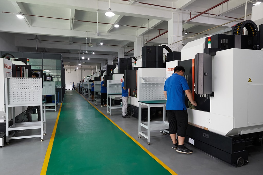
A buyer asking for capability evidence should get a specific answer. The facility behind this guide operates 100+ CNC machines across a 6,800 m2 plant in Dongguan, China, with 100+ staff. The machine list by category:
- 5-axis machining centres (10+) - Mazak VARIAXIS I-600 (510/910/510 mm travel, 12,000 rpm, 22 kW, 71.6 N·m, 30-tool BT40) and Mazak INTEGREX I-250H S (B-axis 0.0001°, 24 kW, 124 N·m, 38-tool HSK-A63). Geared to compound-angle parts, single-setup multi-face prismatic work, and aerospace fittings where datum transfer loss is unacceptable.
- 3-axis / 4-axis machining centres (50+) - Brother SPEEDIO S500Z2N / S700Z2N (10,000 rpm, 14/21-tool ATC, 0.7 s tool-to-tool, Z-axis 2.2 G) and Mazak VCE-430A L / VCE-570C L (10,000 rpm, 118 N·m, 24-tool ATC). Geared to prismatic parts, plates, brackets, housings.
- A 6,800 m² floor of named equipment — Mazak, Brother, Tsugami, Star and Citizen machines (3-axis 50+, 4-axis 20+, 5-axis 20+, 25+ lathes, 7+ grinders, 20+ inspection instruments).
- Tolerance: ±0.002 mm, verified on Hexagon CMMs. Capability is reported per characteristic: Ppk ≥ 1.67 in the initial study and Cpk ≥ 1.33 in production on key and special characteristics (≥ 1.33 on general characteristics). Every report names the feature, its tolerance band, the sample size, the sigma method, and the study window.
- Certified under ISO 9001:2015, IATF 16949:2016 (design excluded) and ISO 14001:2015 — Dongguan Zhuohang Ltd is the invoicing entity behind them.
- Order terms: minimum order one piece, with 3-, 7- or 30-day lead times depending on how involved the part is.
- Machine highlights - VARIAXIS I-600: one-setup multi-face 5-axis + MAZA-CHECK auto-calibration; INTEGREX I-250H S: DONE-IN-ONE mill-turn, B-axis 0.0001° + Ai thermal shield; SPEEDIO S500Z2N / S700Z2N: Z-axis 2.2 G + 0.7 s ATC; Swiss-type: guide-bush switchable + 0.1 µm resolution.
Tolerance bands held: ±0.003 mm on CNC milling, ±0.002 mm on CNC turning, ±0.002 mm on precision grinding and wire EDM. Capability indices: Ppk >= 1.67 initial on key characteristics; Cpk >= 1.33 ongoing in production.
Certifications: ISO 9001:2015 (116024/A/0001/UK/En), IATF 16949:2016 (131941/A/0001/SM/En, design clause 8.3 excluded - disclosed openly), ISO 14001:2015 (116024/B/0001/UK/En). Certificates are issued to Dongguan Zhuohang Ltd (USCC 91441900MA4UWT6X39, established 2005).
Service area: Austria, Belgium, the Czech Republic, Denmark, France, Germany, Greece, Hungary, Ireland, Italy, the Netherlands, Spain, Sweden and the United Kingdom in Europe; Brazil, Canada, Mexico and the United States in the Americas; China, Israel, Japan, Singapore and Sri Lanka in Asia; Australia and New Zealand in Oceania; and South Africa in Africa. Based in China, serving customers worldwide.
Contact: Felipe Iglesias, [email protected], +86 13126536955.
Ready to machine your parts?
Send your drawing to [email protected] or call +86 13126536955 for a quote.
Frequently Asked Questions
What is design for manufacturability?
DFM is the practice of designing a part so it can be machined reliably and economically — sensible wall thicknesses, reachable holes, and tolerances only where function demands. A part designed for the machine costs less and ships faster.
Why does DFM matter before quoting?
A quote prices what the drawing asks for, so a drawing with blanket tight tolerances or unreachable features gets priced high, or scrapped. A DFM review before quoting catches those problems while they are still cheap to fix on the drawing.
What tolerances can you hold?
In short, ±0.003 mm on CNC milling, ±0.002 mm on CNC turning and ±0.002 mm for precision grinding, verified on Hexagon CMMs. The DFM rule is to apply the tight band only to the dimensions that control function, so you pay for precision only where it earns its keep.
What design choices make a part expensive?
Blanket tight tolerances, thin walls, deep holes, and small internal radii each force slower feeds or special tooling. Tolerancing selectively and using the largest allowed radii are the two cheapest DFM fixes on any drawing.
What is the minimum order quantity?
The MOQ is 1 piece, so you can validate a DFM-optimized design with a single prototype before committing to volume, and confirm the design is as easy to machine as the review promised.
What are your lead times?
Roughly 3, 7, or 30 days depending on part complexity and the number of process steps. A part designed for manufacturability runs fewer operations and ships on the shorter end of those tiers.
Does the quote include DFM feedback?
Yes — the quote ships with a design-for-manufacturing review that flags any dimension that cannot be held and any feature driving cost up, before cutting starts, so you can fix the drawing instead of the part.
Which metals do you machine?
Aluminum, stainless steel, carbon and alloy steel, brass, copper, titanium, magnesium, and engineering plastics. Every incoming lot is XRF-checked against its mill certificate, so the grade you design to is the grade you receive.
What is ISO 2768 and how does it help DFM?
In short, ISO 2768 is a general-tolerance standard that lets a drawing state a default tolerance class — f, m, or c — instead of tolerancing every feature. Using it removes blanket tight bands and keeps tight tolerances only on the dimensions that actually control function.
How does surface finish (Ra) affect cost?
Tighter Ra values — 0.8 µm versus 3.2 µm — add finishing passes, slower feeds, and more inspection. The DFM rule is to call the coarsest finish the function allows, so you pay for smoothness only on sealing and bearing surfaces.
How exactly does material choice feed into DFM?
A free-machining grade cuts faster and costs less than a hard alloy, and a stable material moves less after cutting. Material choice is a DFM lever: the grade you specify changes feeds, tooling, and the tolerance the process can hold.
Do you use MIL-STD-105E or ANSI/ASQ Z1.4 sampling inspection?
In short, MIL-STD-105E is the U.S. military sampling inspection standard published in 1989; it specifies acceptable quality limit (AQL) sampling plans for lot-by-lot inspection.
Standards referenced on this page
- ASTM B211/B211M-19 — Standard Specification for Aluminum-Alloy Rolled or Cold Finished Bar, Rod, and Wire
- ASTM A276/A276M-17 — Standard Specification for Stainless Steel Bars and Shapes
- ISO 9001 — Quality management systems — Requirements